
Matteo Piano
Software Security Engineer
Quite a lot of progress happened from the first post, but I have not felt the necessity to write about it since most of the code I wrote is just boilerplate to setup the environment. Just to make short summary:
Now that the foundations have been built, we can start drawing meshes on the screen. The building block will be the Vertex data structure which represents a point in 3D space with its normal vector and corresponding texture coordinates.
struct Vertex {
    glm::vec3 position;     // Position of the vertex in 3D space
    glm::vec2 texCoord;     // UV texture coordinate
    glm::vec3 normal;       // Normal vector to the surface the vertex defines
};
With this piece of data defined, the next step is to write shader code to instruct the GPU on how to handle it.
The Vertex Shader is going to take as input the vertex data and the various model-view-perspective parameters and evaluate the vertex projection. Moreover, to allow the following lighting calculation, the vertex components will also be transformed in varying data which will then be automatically interpolated and passed to the Fragment Shader
attribute vec3 position;        // Position of the vertex
attribute vec2 texCoord;        // UV texture coordinates
attribute vec3 normal;          // Normal vector to the vertex

varying vec2 texCoord0;         // To interpolate UV values
varying vec3 position0;         // To interpolate position values
varying vec3 normal0;           // To interpolate normal values

uniform mat4 perspective;       // Camera perspective matrix
uniform mat4 model;             // Transformation matrix
uniform mat4 view;              // Camera view matrix

void main() {
    // Evaluate model view matrix
    mat4 model_view = view * model;
    // Evaluate vertex projection
    gl_Position = perspective * model_view * vec4(position, 1.0);
    // Copy values to interpolate
    position0 = (model_view * vec4(position, 1.0)).xyz;
    normal0 = transpose(inverse(mat3(model_view))) * normal;
    texCoord0 = texCoord;
}
The Fragment Shader implements Lambertian lighting model to evaluate the color of a pixel. It takes as input the texture data, the light position and intensity and the interpolated values passed from the Vertex Shader.
varying vec2 texCoord0;             // Interpolated UV texture coordinate
varying vec3 position0;             // Interpolated vertex position
varying vec3 normal0;               // Interpolated vertex normal

uniform sampler2D diffuse;          // Texture
uniform vec3 light_pos;             // Position of omni light in 3D space
uniform float light_intensity;      // Intensity of omni light

void main() {
    // Evaluate light ray
    vec3 r = (position0 - light_pos);
    // Evaluate direct illumination
    float direct = light_intensity * max(-dot(normalize(r), normal0), 0.0) / (4 * 3.14 * dot(r, r));
    // Evaluate fragment color
    gl_FragColor = texture2D(diffuse, texCoord0) * (direct + 0.1);
}
Now all the pieces of the puzzle are in place and it is possible to actually start sending data to the GPU. My first draw attempt was dome by simply sending a buffer with 3 vertices and using GL_TRIANGLES as draw method (as you may notice, I chose the Swedish flag as texture):

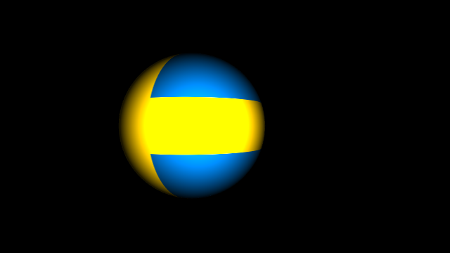
A textured triangle is nice but not too much interesting, so the next mesh I tried to draw was a sphere. I achieved that by creating a bi-dimensional array of vertices and by disposing them using spherical coordinates. To effectively display the mesh, I took each couple of rows in the bi-dimensional array and rendered that using GL_TRIANGLE_STRIP as draw method. And, again, I used the Swedish flag as texture:
The system seems ready to display more or less any kind of geometry. The next step will be to add the possibility for the user to move around and explore the scene. After that, everything will be ready to start working on creating a small physics system for cloth simulation.